Individual —
■ Steel■ Magnet□ Void
Mean torque—Nm
Torque ripple—Nm
Maximum stress—MPa
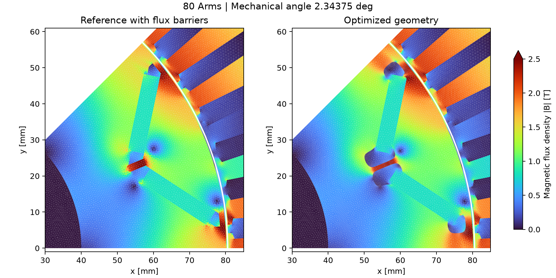
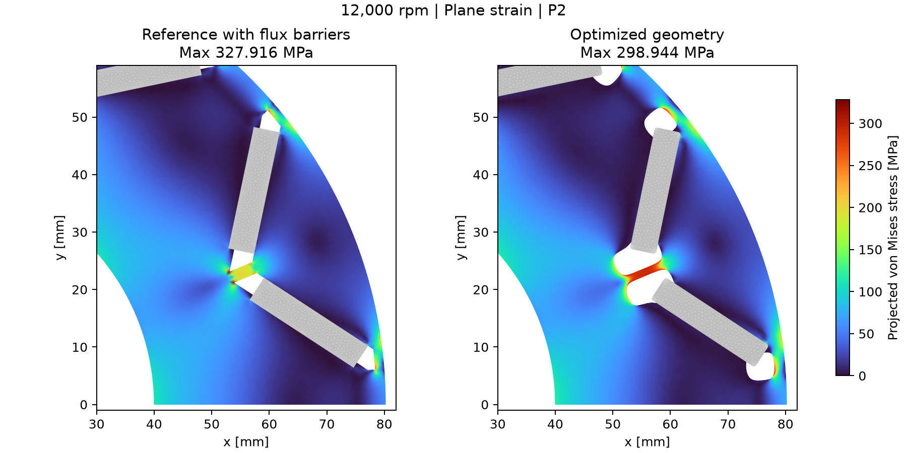
Magnetic flux density, stress distributions and torque waveforms for the representative solution are shown in the reference comparison below.
TOPOLOGY OPTIMIZATION / RESEARCH ATLAS
Explore the distribution of steel and voids in a motor while considering magnetic fields and stress.
Discover the final Pareto solutions obtained with the NGnet on/off method and the role of their geometry.
01 / PARETO EXPLORER
Maximize mean torque · Minimize torque ripple
Constraint: maximum von Mises stress ≤ 300 MPa
Click a point to display its geometry.
Focus a point and press Enter to select it. All individuals are also available in the list below.
Magnetic flux density, stress distributions and torque waveforms for the representative solution are shown in the reference comparison below.
OPTIMIZATION HISTORY
A 24.5-second video shows the Pareto front and representative geometries across 200 generations. Each generation’s representative is selected near 110 Nm; this is not a parent–offspring lineage.
Labels within the video are in Japanese.
02 / METHOD
Instead of switching many elements directly ON or OFF,
the weights of Gaussian basis functions serve as design variables.
100 Gaussian basis functions; covariance parameter 2×10⁻⁶ m². Material distribution varies within the design region while fixed regions, including magnets, are preserved.
Gaussian weights determine the positions, shapes, and connectivity of holes. The symmetric fundamental region is repeated to construct the full motor geometry.
Nonlinear magnetic analysis gives torque at each rotor position. P2 elements evaluate the maximum von Mises stress caused by centrifugal force.
Solutions balance maximizing mean torque and minimizing peak-to-peak torque ripple. Violations of stress and other constraints receive penalties.
Method background: Sato et al., Topology optimization of an IPM motor using NGnet (2015). The numerical values and geometries on this site are results of this project.
BOUNDARY RESOLUTION
Geometry discretization affects local stress evaluation. The NGnet function is re-evaluated at added nodes to resolve material boundaries, rather than merely increasing the element count.
Material presence is evaluated at the added nodes to locate the boundary.
Fillet radius: 0.5 mm; 16 segments per 90° arc. Bonded and separated interfaces are preserved.
Only eligible short free edges near bonded endpoints are snapped, with connectivity and element-quality checks.
Takenouchi, Hiruma and colleagues report IPM motor optimization with stress, connectivity, and mesh-quality constraints, using boundary-fitted meshes for accurate magnetic and elastic analyses. We cite their work for its relevance to remeshing and stress evaluation.
K. Takenouchi, S. Hiruma, T. Mifune and T. Matsuo (2024), Topology and parameter optimization of IPM motor considering mechanical strength by stress and connection constraints, COMPEL, 43(4), 839–851.
DOI: 10.1108/COMPEL-11-2023-0551 · Hokkaido University Repository
The validation values below and the optimization results on this site are from this project, not from the cited paper.
03 / REFERENCE TOPOLOGY
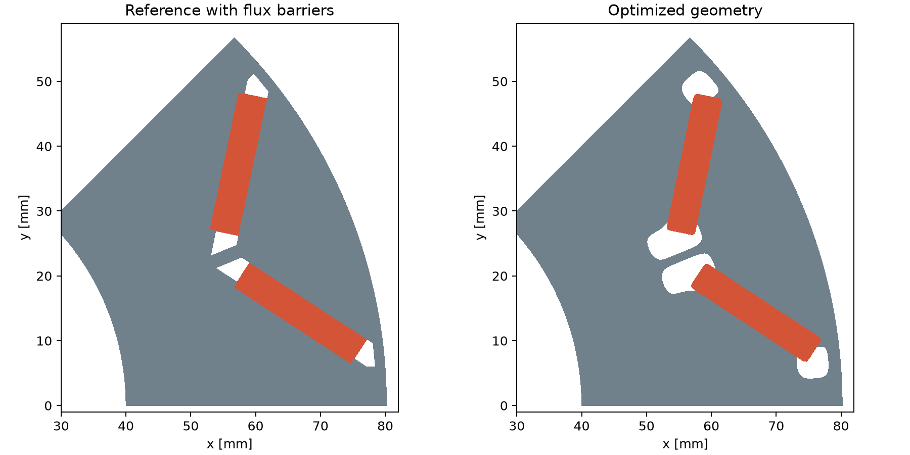
The reference is an 8-pole, 48-slot interior permanent magnet motor. The V-shaped magnet arrangement is fixed while the rotor steel distribution is optimized.
The reference geometry on the right has flux barriers at both ends of each magnet. It was generated from the original CAD and analyzed for magnetic fields and stress at 80 Arms and an axial length of 50 mm.
Rotor reconstructed by symmetry. Gray: design steel; red: magnets.
04 / REFERENCE COMPARISON
A representative final-generation solution (mean torque 110.247 Nm, ripple 4.264 Nm) was selected
and re-evaluated with the reference geometry using 64 intervals.
The reference geometry follows the mesh figure of the IEEJ public motor model and retains the magnet-end flux barriers from the original CAD.
| Geometry | Mean torque Nm | Ripple Nm | Maximum stress MPa |
|---|---|---|---|
| Reference (with flux barriers) | 109.070 | 17.368 | 327.916 |
| Optimized geometry | 110.263 | 4.526 | 298.944 |
Maximum stress is nodally projected von Mises stress. Values above 300 MPa are highlighted in red.

Comparison results CSV ↓ 64-point torque waveforms CSV ↓
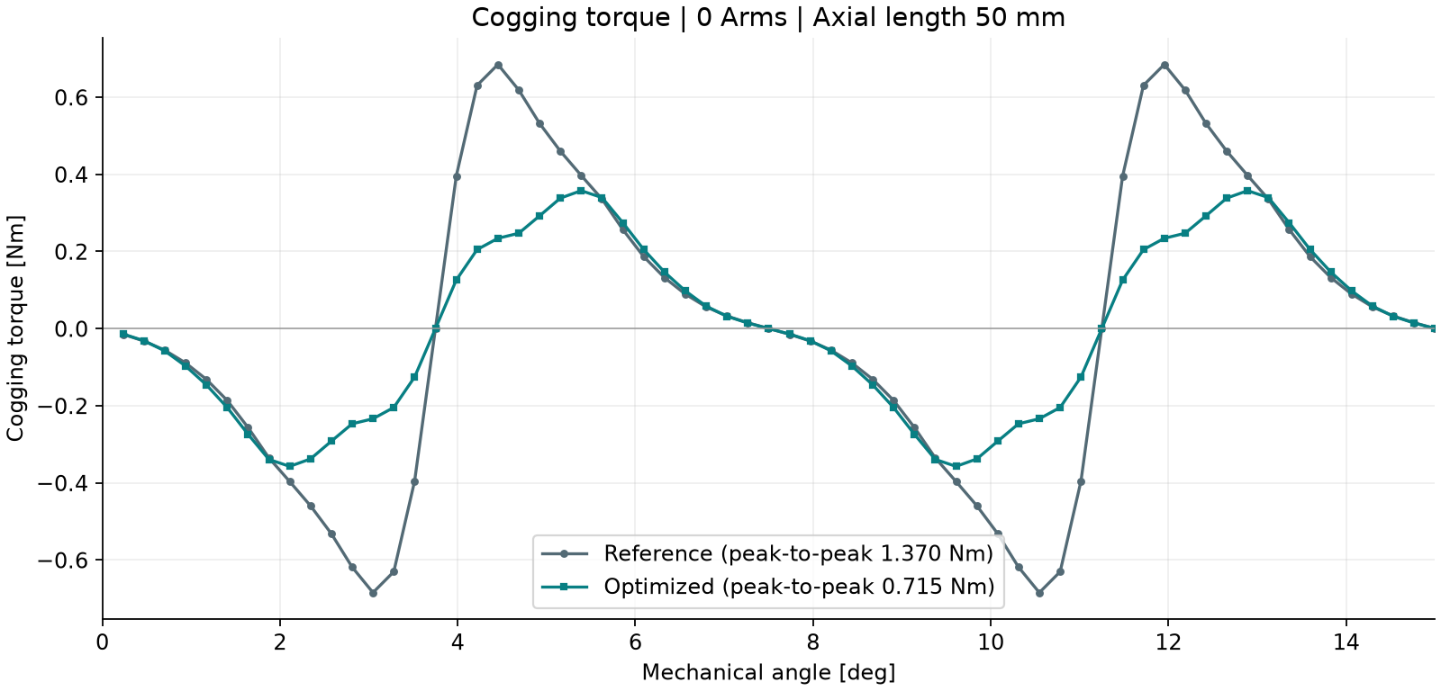
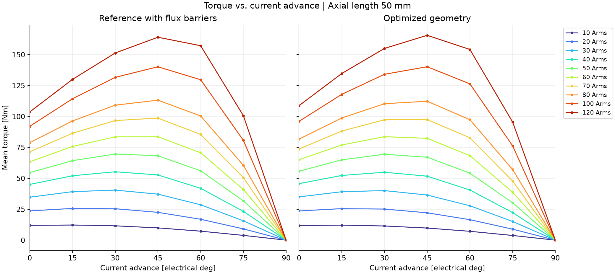
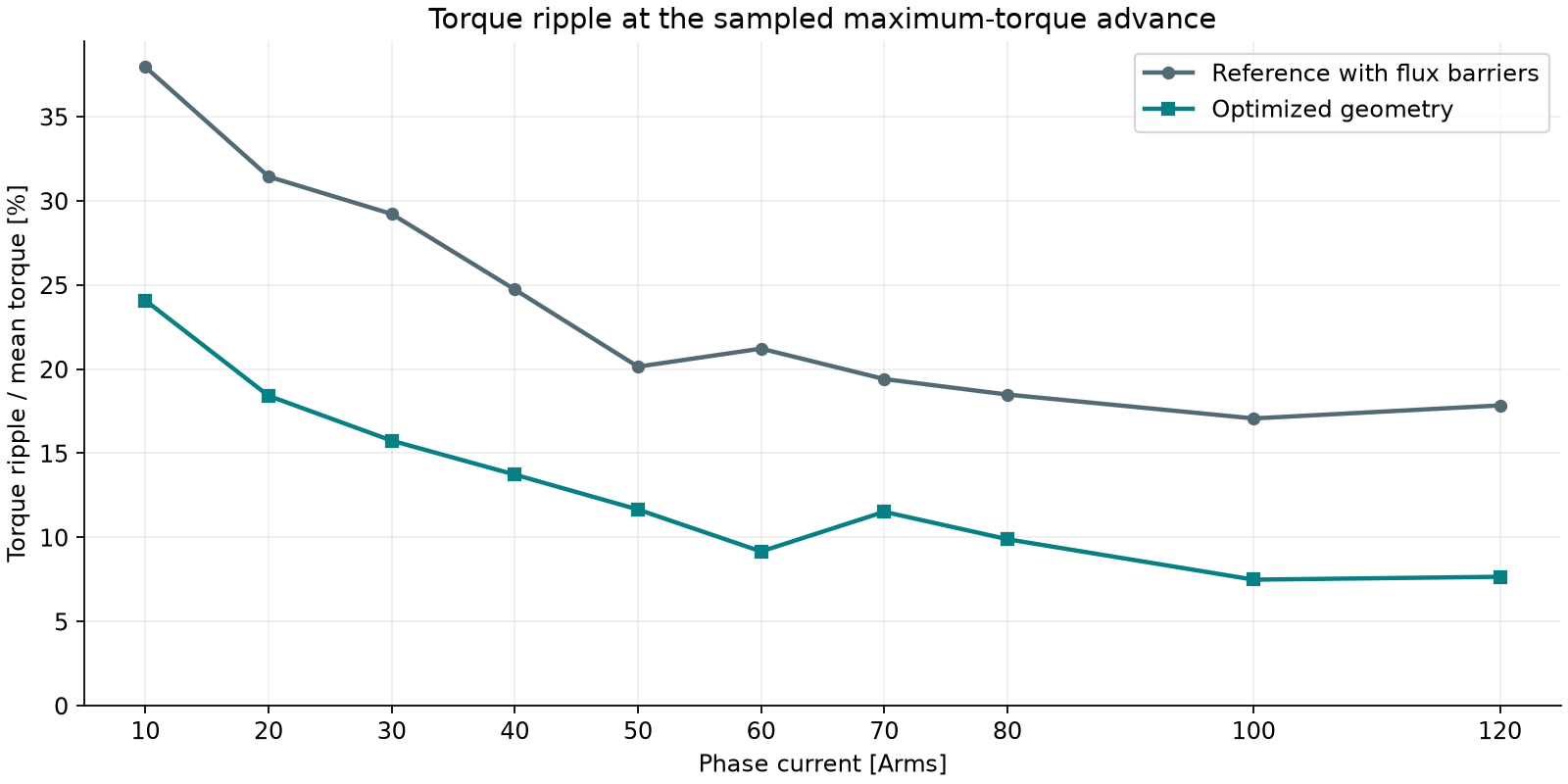
Cogging torque CSV ↓ Torque–advance curves CSV ↓ Ripple at maximum torque CSV ↓
05 / INDUSTRY–ACADEMIA COLLABORATION
We welcome inquiries about industry–academia collaboration on motor topology optimization and design considering magnetic fields and mechanical stress.
Each individual in this optimization required 17 magnetic-analysis steps, remeshing, and one stress-analysis step. Estimated cloud computing costs for 200 generations using services such as AWS are shown below.
| Individuals per generation | Generations | Estimated computing cost |
|---|---|---|
| 640 individuals | 200 generations | Approx. JPY 30,000 |
| 1,024 individuals | 200 generations | Approx. JPY 50,000 |
These are indicative cloud computing costs. Actual costs depend on the analysis conditions, cloud configuration, and service rates.